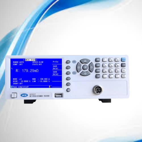
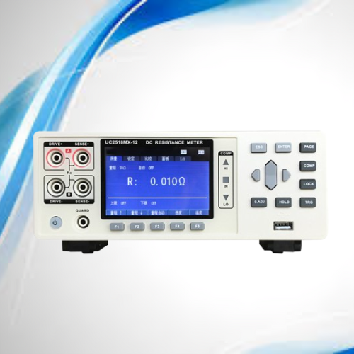
UC2518-18A DC Resistance Tester

The UC2518 Series DC Low Resistance Tester is a high-speed, high-precision resistance measurement instrument with advanced temperature compensation and temperature conversion functions. It is ideal for production line testing, quality inspection, laboratory measurement, and automated test systems.
Model Range
- UC2518: 1 μΩ – 10 MΩ
- UC2518A: 10 μΩ – 200 kΩ
Performance Characteristics
- 4.3-inch TFT LCD display (480 × 272 RGB resolution)
- Direct U-disk storage for test results
- Maximum resistance accuracy up to 0.05%
- Built-in comparator with HI / LO / IN sorting
- Temperature compensation and temperature conversion functions
- Temperature basic accuracy: 0.1℃
- Statistical functions: Cp, CpK and other analysis
- 100+ internal setting files, expandable to 500+ via U-disk
- Firmware upgrade via USB HOST
- Supports FAT16 / FAT32 file systems
- Standard HANDLER, USB HOST, USBCDC, USBTMC interfaces
- Optional RS232C and GPIB interfaces
Applications
Suitable for testing coil, inductor, transformer, voice coil, relay contact resistance, connector resistance, fuse resistance, cable resistance, PCB resistance, welding resistance, conductive film, and metal resistance. Temperature compensation eliminates temperature effects during measurement.
General Specifications
| Operating Temperature / Humidity |
0°C – 40°C, ≤85% RH |
| Power Supply Voltage |
198V – 242V AC |
| Power Frequency |
47.5Hz – 63Hz |
| Power Consumption |
≤ 30 VA |
| Dimensions (W × H × D) |
240 × 100 × 345 mm |
| Weight |
Approx. 2 kg |
Measurement & Function Specifications
| Basic Accuracy |
0.05% + 2 digits (2MΩ: 0.2%, 10MΩ: 0.3%) |
| Measuring Speed (50Hz) |
Fast: 22ms / 2.7ms, Medium: 42ms, Slow: 102ms |
| Measuring Speed (60Hz) |
Fast: 18.5ms / 2.7ms, Medium: 35ms, Slow: 102ms |
| Statistics |
Cp, CpK statistical analysis |
| Range Selection |
Automatic / Hold / Manual |
| Trigger Mode |
Internal / External |
| Averaging |
1 – 255 times |
| Delay Time |
0 – 9999 ms (1 ms step) |
| Calibration |
Short circuit, zero, load correction |
| Test Configuration |
4-terminal Kelvin measurement |
| Display Mode |
Direct reading, Δ% |
Resistance Range & Measuring Current (UC2518)
| Range |
Test Current |
Measurement Range |
| 20 mΩ |
1 A |
1 μΩ – 20 mΩ |
| 200 mΩ |
100 mA |
20 mΩ – 200 mΩ |
| 2 Ω |
100 mA |
200 mΩ – 2 Ω |
| 20 Ω |
10 mA |
2 Ω – 20 Ω |
| 200 Ω |
1 mA |
20 Ω – 200 Ω |
| 2 kΩ |
100 μA |
200 Ω – 2 kΩ |
| 20 kΩ |
100 μA |
2 kΩ – 20 kΩ |
| 200 kΩ |
10 μA |
20 kΩ – 200 kΩ |
| 2 MΩ |
1 μA |
200 kΩ – 2 MΩ |
| 10 MΩ |
100 nA |
2 MΩ – 10 MΩ |
Temperature Measurement & Compensation
| Temperature Accuracy |
0.1℃ |
| Measurement Time |
100 ±10 ms |
| Temperature Sensor |
Pt sensor, -10.0℃ – 99.9℃ |
| Analog Input |
0 – 2 V (−99.9℃ – 999.9℃) |
| Temperature Compensation |
Converts resistance to set reference temperature |
| Temperature Conversion |
Converts resistance change into temperature change |
Standard Accessories
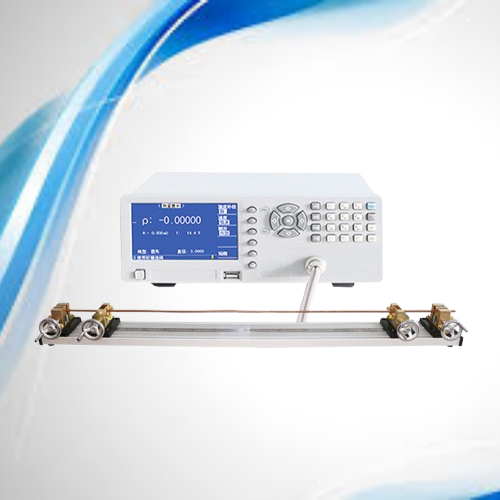
- UC9541 Temperature probe (Pt)
- UC26004-1 Four-terminal Kelvin test cable
Optional Accessories
- UC26001A Five-terminal test box
- UC26009B SMD patch test clip
- UC6801-01 Pedal start switch